Reactor Process Flow Diagram Process Flow Diagram Of Industr
Sodium-cooled fast reactor Schematic representation of the reactor in a flow diagram used. (1) gas Review of plug flow reactor diagram ideas
Plug Flow Reactor Design
The process flow diagram of jacketed reactor. Reactor configurations Process reactors selection guide: types, features, applications
Reactor industrial
Reactor distillation batch time determine rate theoretical cycle calculate required way pharma system engineeringPlug flow reactor design [diagram] process flow diagram reactorProcess flow diagram of industrial loop reactor.
| process flow diagram (pfd) of mechanically mixed reactor (adaptedTheoretical way to determine the time required for distillation in Flow reactor configurations for more advanced systems.[diagram] process flow diagram reactor.

Difference between batch reactor, cstr, and pfr
Reactor flow plug pfr mass reactors continuous inlet continuouslyReactor bed Process flow diagram of reactor system used for all experiments[diagram] process flow diagram reactor.
Schematic diagram of the continuous-flow reactor system.Process reactor reactors components engineering processing raymer batch manufacturing information credit equipment tanks Reactor experimentsReactor sodium cooled liquid breeder reactors type britannica pressurized physics druckwasserreaktor boiling.

Process flow diagram for (a) a two-bed series reactor (sr-2) and (b) a
Process flow diagram around the reactorPlug flow reactor design Continuous reactorReactor heterogeneous photocatalytic.
Figure s1 . schematic of the flow-through reactor system.Process flow diagram for experimental reactor Reactor schematic laboratoryFlow diagram of the experimental setup. the reactor was 45 cm â 20 cm â.

Plug flow reactor (pfr) : mass balance and reaction speed
Schematic diagram of the continuous-flow reactor system at laboratory[diagram] process flow diagram reactor Schematic diagram of the continuous flow reactor system[diagram] process flow diagram reactor.
Process flow diagram for the parallel reactor configuration.Schematic reactor representation cylinders pressure regulator cp Process flow diagram for the reactor train used in this study| process flow diagram (pfd) of mechanically mixed reactor (adapted.
![[DIAGRAM] Process Flow Diagram Reactor - MYDIAGRAM.ONLINE](https://i2.wp.com/wiki.zero-emissions.at/images/1/14/Flow_diagram_of_the_polypropylene_horizontal_reactor_gas_phase_process.jpg)
Nuclear reactor labeled diagram
Nuclear reactorSchematic diagram of reactor [diagram] process flow diagram reactorReactor schematic.
Schematic diagram of the flow-type reactor used for the heterogeneousReactor pressurized section reactors coolant types britannica outlets inlets passing .

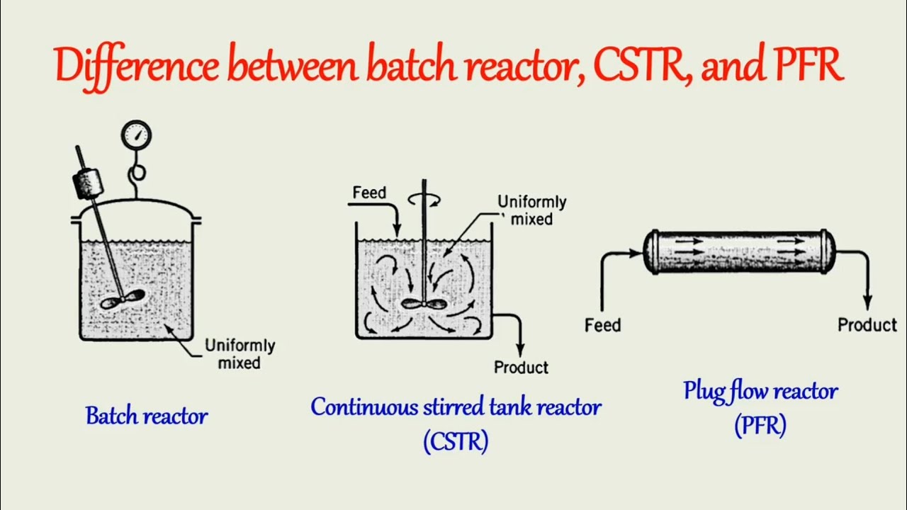
Difference between batch reactor, CSTR, and PFR | Chemical reaction

Theoretical Way to determine the time required for Distillation in

Schematic representation of the reactor in a flow diagram used. (1) Gas

| Process Flow Diagram (PFD) of mechanically mixed reactor (adapted
![[DIAGRAM] Process Flow Diagram Reactor - MYDIAGRAM.ONLINE](https://i2.wp.com/www.hitachi-hgne-uk-abwr.co.uk/images/reactor/intro/abwr_diagram.png)
[DIAGRAM] Process Flow Diagram Reactor - MYDIAGRAM.ONLINE

Plug Flow Reactor Design

Flow diagram of the experimental setup. The reactor was 45 cm  20 cm Â